Troubleshooting the Hot Wire CNC Foam Cutter
You just built your Hot Wire CNC foam cutter, but it’s not working as expected. I receive questions from people worldwide who have had issues getting their machines up and running.
USB Driver problems
Recently (December 2024), several users of the CNC Foam cutter reported problems. Check this post, USB CH340 Driver Problems A recent Windows Update is the reason for this. The post provides instructions on how to resolve the issue.
Where to Start?
Please check the e-book and troubleshooting videos before asking any questions most are answered there.
The troubleshooting video below used the older firmware and software, but the rest of the information still applies to the latest versions.

There are now Electronic build guides for each supported controller. Check these first to make sure you have followed the same procedures.
- Electronics Build Guide Arduino Mega 2560 RAMPS 1.4
- Electronics Build Guide MKS Gen L V1 and V2
- Electronics Build Guide BTT SKR Pico
The USB CNC foam cutter build was initially released in July 2019 and has been updated several times. The latest release, which also supports 32-bit grblHAL, was released in Nov 2023. It’s proved very popular, and many of you have downloaded the ebook and plans and built the design with some cool variations.
So if yours is not working as you expected, this post will take you through the troubleshooting steps. If it still doesn’t work, send me some details with a few pictures, and I’ll do my best to get you up and running.
So let’s troubleshoot some of the common issues. I made a video covering the common question which may help as well.
Before we start, let’s cover some basics.
Recommended Parts for the Hot Wire CNC Foam Cutter
Ensure you have used the parts I have or something similar. If you are doing something else, I may be unable to help. https://rckeith.co.uk/parts-list-cnc-foam-cutter/
Can I use the Arduino Uno?
You can if you use the DevFoam CNC firmware, but not with the firmware on this site. It’s only for Arduino Mega 2560-based controller boards and the SKR Pico 32-bit.
Check your power supply
The foam cutter does need one. The power from the USB port on our computer isn’t enough to drive the stepper motors. Ensure you have a minimum 150-watt power supply connected to the controller board. Check the ebook and parts list for details on how to size the power supply. Most 3d printer power supplies will be more than enough for this design using NEMA17 stepper motors

Start simple
What do I mean by this? Well, you just received all your parts and it doesn’t work as expected after putting it all together. Where is the problem? Not easy to find if. So take it step by step checking each part as you add it.
As I show in the videos we start with the mainboard check that works and then add the RAMPS board check that and then add the drivers check them and then connect the motors.
That way if something is wrong you should find it before moving on.
Windows can’t detect the board
If you’re unable to connect to your board with XLoader to upload firmware, it may be due to a missing or incompatible driver for the CH340 serial chip.
Solution:
- Verify Driver Installation:
- On Windows, open Device Manager (press
Win + Xand select Device Manager). - Under Ports (COM & LPT), check for a device labelled as CH340 or a similar name.
- If there’s a yellow exclamation mark, the driver is missing or faulty.
- On Windows, open Device Manager (press
- Install CH340 Drivers:
- Visit the SparkFun tutorial for installing CH340 drivers: How to Install CH340 Drivers.
- Download the appropriate driver for your operating system.
- Follow the step-by-step instructions in the tutorial to install the driver.
- Reconnect Your Board:
- After installing the driver, unplug and reconnect your board.
- Check Device Manager again to confirm the board is recognized and assigned a COM port.
- Retry Firmware Upload:
- Open XLoader, select the correct COM port and attempt to upload the firmware again.
By following these steps, you should be able to resolve the issue.
Checking for a faulty Arduino Mega 2560 or MKS board
Receiving a faulty board is quite rare but does happen occasionally. The way I check if a board is OK is to download the Arduino IDE and upload the example blink sketch. My video here shows how to do this https://www.youtube.com/watch?v=yzCKXei0pLU&t=1003s . If this works OK then most likely you have a faulty driver. This is quite common and several guys have had this
Checking 32-bit board
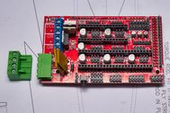
I’ve only used the SKR-Pico 32-bit board. Check the fuse on the board if nothing appears to be working. Make sure you remove the boot jumper and USB power jumper after uploading the firmware. USB power will not run the stepper motors.

Check that the Firmware has been uploaded OK
The firmware is now pre-compiled on the website. This posting has all the details of how to upload the firmware and confirm it is working https://rckeith.co.uk/easy-way-to-upload-cnc-foam-cutter-firmware/
DRO’s are not working as expected
Sometimes, the DRO (Digital Read Out) might not display any numbers. This can happen if the EEPROM settings are damaged. To fix this, open the MDI Dialogue box and type this command: $RST=*
This issue often happens because of the previous firmware on the board. Running the command mentioned above will reset the settings to the firmware defaults. If you customise any settings, you’ll need to enter them again. If you have a backup, the latest software can help you restore it.
Stepper motors are not turning
This is probably one of the most common issues and can be caused by a few things.
- The cables used to connect the stepper motors to the RAMPS or the MKS board are wired incorrectly.
The 4-wire cables used on the NEMA 17 have a 6 and 4-pin connector. Sometimes these are not wired to the correct pins. Make sure they are wired as shown.
Common colour codes are Green/Black goes to A+A- and Red/Blue to B+B- - Faulty drivers can cause an axis not to work. Make sure you have inserted them the correct way. Aligning the Enable pin on the driver with the Enable socket on the board. If you power on without it aligned the driver will be destroyed.
- VRef is too low. You need to adjust the Voltage Reference (VRef) to match the stepper motor to supply enough current otherwise, it won’t work. Supplying too much can damage the motors or drivers. Check my video here on how to do this https://www.youtube.com/watch?v=zbESZLDxY20&t=1790s
- Faulty RAMPS board. This is quite rare, but sometimes the fuses can blow or you have a bad board. The only option, if you have tried everything else, is to try another one. The fuses can be replaced if you are good with a soldering iron.
Homing Issues
This is a common question, so I have created a separate post which goes into some detail. Troubleshooting CNC Homing
One Axis is not working
The most common axis is the 4th, which is now the A-axis. The ground pin for this axis is not next to the signal pin like the X, Y and Z axes. Check the connections
Using the wrong firmware will cause this. In the status window, make sure you see AXS :4: XYZA. If you see AXS: 4: XYZU, you have the older firmware, which has been retired.

Strange behaviour
This usually happens if you’re not using screened or shielded cables. Stepper motors can create false signals in the switch wiring due to their back EMF (electromotive force). I experienced this problem, and switching to screened cables solved it.
Stepper motors produce a lot of energy, and some of it can cause interference in the wiring of limit switches.
Foam pieces of the incorrect size
Inaccurate foam piece sizes are typically caused by machine calibration or micro-stepping settings. Since the firmware is compiled for 1/8th stepping, the jumpers or DIP switches must be adjusted to match.
Micro-stepping
If you’ve built the machine with the same components I used and in the recommended parts list, then the pre-compiled firmware will have the correct settings. But we still need to check it.
If you change the micro-stepping, the steps/mm need to be recalculated. See the calibration section next
Calibration
If you have used different threaded rods or lead screws, then the steps/mm setting will need to be adjusted to suit.
The video shown below explains how to check the calibration.
The website has a calculator to work out a new value for steps/mm https://rckeith.co.uk/calibrating-the-hot-wire-cnc-foam-cutter/
The kerf is the amount of foam melted away by the hot wire. If the kerf isn’t properly accounted for in your g-code software, your piece might turn out smaller than expected. Make sure to double-check the kerf value you’re using.
I’ve made a video that shows how to find the right kerf value. You can watch it here: https://www.youtube.com/watch?v=FNs7jCHkPqc&t=4783s.
Hot Wire problems
If you are having trouble getting enough heat into the wire, then the following may be the cause.
- The wire is too thick in diameter. I use a 0.4mm wire if you use bigger then more current is needed. The RAMPS or MKS board may not be able to supply.
You can change your wire for thinner or use a separate power supply for the wire that can supply the current. Or use the MKS board with a 24-volt power supply. - The wire is too long. If the distance between the carriages is over 1 meter or 39 inches then you will need more power for the wire. The MKS board with a 24-volt power supply can help here. Going from 12 to 24 volts means the current is reduced, and this usually gets the wire hot enough.
Summary
These are the most common questions people email me about. If you are still having issues then drop me an email via the contact page and I’ll do my best to help you.
Please check the videos listed and the configuration page before emailing me. If your problem is covered in these I will direct you there first.
Happy foam cutting