
Troubleshooting CNC Homing
If you’ve just finished building your CNC and turned on homing for the first time — only to find it’s not working right — don’t worry. This is one of the most common hiccups new builders run into. The good news is, it’s usually something simple, like a wiring issue or a small setting that needs tweaking. Let’s walk through it step-by-step so you can get homing working properly.
Homing tells your CNC where ‘zero’ is — the reference point for all movements. If it’s off, your cuts and moves will be too
Start With These Checks
Before digging deeper, go through these quick basics:
- Make sure you’re using the latest firmware and software.
Old versions sometimes use different pinouts or settings that can mess with homing. - Use shielded or screened cables for your limit switches.
Electrical noise can cause false triggers, especially on long cable runs. - Wire the switches as NC (Normally Closed).
This way, the controller knows if a wire breaks or disconnects — it’s safer and more reliable. - Only connect Ground and Signal to the controller pins.
Don’t connect 5V — it’s not needed for most setups. - Ground the cable shield at the controller end only.
Grounding both ends can cause electrical interference. - Test axis directions before enabling homing.
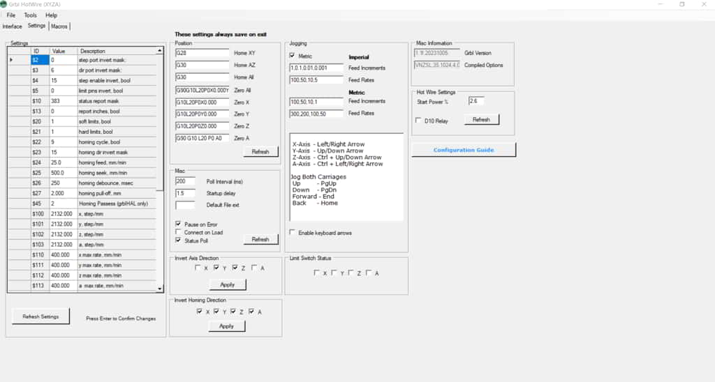
Set$22=0temporarily and use manual jogs to make sure each axis moves the right way. Once confirmed, set$22=1to enable homing.
Limit Switch Pins
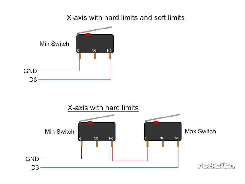
Limit switches should be wired between ground (-) and the signal (S) pins on your controller.
For Arduino-based boards (including MKS Gen L V1 and V2):
| Axis | Pin min |
|---|---|
| (X) | D3 |
| (Y) | D14 |
| (Z) | D18 |
| (A) | D49 |
Connect each switch between Signal (S) and Negative (-).
For example, the A-min switch uses D49 as the signal pin — connect the other wire to a nearby negative pin (like the one beside Z-min).
Limit Switch Status
Once homing is enabled, check your limit switch indicators in the software. None of the boxes should be marked “triggered.”
If one or more are showing triggered when they shouldn’t, try this:
- Make sure
$5=1— This tells the controller your switches are “Normally Closed.” - If it’s still triggered, you likely have an open circuit. Common causes include:
- The switch is wired between Common and NO (Normally Open) instead of NC.
- There’s a break or loose connection in the cable.
- The axis is physically pressing a switch open.

⚙️ Default Homing Settings
Compare your GRBL settings to these defaults — most homing issues trace back here:
| Setting | Value | Comment |
|---|---|---|
| $5 | 1 | NC(normally closed) |
| $22 | 1 | Enable Homing – Set to 9 for the SKR Pico Board |
| $26 | 5-25 milliseconds | Debounce setting see below |
| $27 | 2-10mm | Axis pull off |
| $20 | 1 | Soft Limits (if using 4 switches. Leave at 0 if you use 8 switches) |
| $21 | 1 | Hard Limits |
| $23 | Varies | Changes homing direction. Use the setting tab to invert |
| $130-$133 | Max Travel(mm) | How far each axis moves Only use with Soft Limits. If you leave at 0 axes won’t move |
🚨 Common Issues
If you’ve checked everything above and homing still doesn’t behave, it’s almost always one of these:
- A broken wire or a poor crimp connection
- Unshielded or noisy cables are causing false triggers
- Incorrect GRBL settings (especially
$5,$22, or$23) - Outdated firmware (pin assignments can change between versions)
💡 Final Tips
Still stuck? Try these quick troubleshooting moves:
- Disconnect all switches and reconnect them one at a time to find the bad one.
- Jog each axis manually with
$22=0to confirm direction and limit switch response. - Double-check your wiring against the controller diagram — it’s easy to miss one pin.
Once everything lines up, your CNC should home smoothly every time. Take it slow, make small changes, and don’t get discouraged — you’re just a few tweaks away from a perfectly homing machine!
Happy Foam Cutting


