
Electronics Build Guide BTT SKR Pico
This guide provides step-by-step instructions for building the electronic components of a CNC foam cutter. The BTT (BigTreeTech) SKR Pico board, which features the Raspberry Pi RP2040 32-bit processor, is commonly used in Voron 3D printers. I now use this microcontroller on my CNC foam cutter, running the grblHAL firmware.
Thanks to advancements in 3D printing, the electronics for a foam cutter are now affordable and easy to source
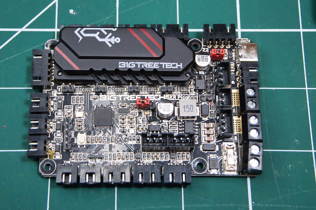
SKR Pico 32-bit
The SKR Pico microcontroller offers several advantages for CNC foam cutting
- Powerful and Efficient Processing Powerful and Efficient ProcessingPowerful and Efficient ProcessingThe SKR Pico uses the RP2040, a 32-bit dual-core ARM Cortex-M0+ processor, providing sufficient processing power for precise, real-time control over CNC movements.
- Compact Size The SKR Pico is a small, compact board, making it ideal for space-constrained setups. Its minimal footprint allows for easier integration into the CNC foam cutter’s electronics compartment without sacrificing performance.
- Cost-Effective The SKR Pico is relatively affordable compared to other high-performance CNC controllers. The embedded TMC2209 stepper drivers help keep the cost down. It can be cheaper than an 8-bit MKS Gen L board.
- 12 or 24-volt Operation allows the use of hot wires longer than 39 inches or 1 meter
- Larger G-Code File Handling: The increased memory available in 32-bit microcontrollers allows grblHAL to handle larger and more complex G-code files without running into memory limitations. This is particularly useful for large CNC jobs that require a lot of toolpath data.
- Configuration: The driver current and microstepping can be configured on the settings page of GRBL Hotwire. There is no need to fiddle with trim pots and pin jumpers.
Are there any disadvantages if you choose the BTT SKR Pico
- Embedded Drivers. Although this makes for a very cost-effective board, if one of the drivers fails, the whole board will need to be replaced.
Build Guide
Please make sure you have used the recommended parts from the parts list. If you use alternatives, this guide may not work.
Please don’t install the electronics onto the foam cutter until it’s working on the bench. After the bench test, you can do the final calibration and dry run once installed on the foam cutter. The foam cutter will require longer wires than your bench testing, which is usually the source of problems if it doesn’t work correctly when installed
Please note that Homing can’t be tested on the bench. It’s only possible after installation on the foam cutter with all the switches wired.
Step 1 – Connect the board
Connect the board to your computer running Windows 10 or 11. I can’t confirm if it will run on older versions of Windows because I don’t use them anymore.
If you can’t detect the board, then ensure you have the jumper for USB power bridged.

Step 2 – Firmware
Download the firmware and software from here and unzip them to your computer. In the location, you unzipped the download, then unzip grblHAL.zip

Unzip grblHAL.zip to a suitable location. This will save the file

When you connect the board, you should see an extra drive. Just copy the grbHAL.uf2 onto the drive, and the board will reboot. Remove the jumpers.
Default Settings
| ID | Value | Description |
|---|---|---|
| $0 | 10.0 | step pulse usec |
| $1 | 255 | step idle delay msec |
| $2 | 0 | step port invert mask: |
| $3 | 6 | dir port invert mask: |
| $4 | 15 | step enable invert bool |
| $5 | 0 | limit pins invert bool |
| $10 | 383 | status report mask |
| $13 | 0 | report inches bool |
| $20 | 0 | soft limits bool |
| $21 | 0 | hard limits bool |
| $22 | 0 | homing cycle bool |
| $23 | 15 | homing dir invert mask |
| $24 | 25.0 | homing feed mm/min |
| $25 | 500.0 | homing seek mm/min |
| $26 | 250 | homing debounce msec |
| $27 | 1.000 | homing pull-off mm |
| $100 | 2132.000 | x step/mm |
| $101 | 2132.000 | y step/mm |
| $102 | 2132.000 | z step/mm |
| $103 | 2132.000 | a step/mm |
| $110 | 400.000 | x max rate mm/min |
| $111 | 400.000 | y max rate mm/min |
| $112 | 400.000 | z max rate mm/min |
| $113 | 400.000 | a max rate mm/min |
| $120 | 10.000 | x accel mm/sec^2 |
| $121 | 10.000 | y accel mm/sec^2 |
| $122 | 10.000 | z accel mm/sec^2 |
| $123 | 10.000 | a accel mm/sec^2 |
| $130 | 600.000 | x max travel mm |
| $131 | 300.000 | y max travel mm |
| $132 | 300.000 | z max travel mm |
| $133 | 600.000 | a max travel mm |
| $140 | 500 | x-axis current mAh |
| $141 | 500 | y-axis current mAh |
| $142 | 500 | z-axis current mAh |
| $143 | 500 | a-axis current mAh |
| $150 | 16 | x-axis microsteps |
| $151 | 16 | y-axis microsteps |
| $152 | 16 | z-axis microsteps |
| $153 | 16 | a-axis microsteps |
Step 3 – Software
From the downloaded file, unzip grblHotwire.zip to a folder. Then run the setup.exe
This will install the software so that we can complete the rest of the bench testing.
In the software, if your COM port is not selected, press ReScan and click Connect. You should see the image below. Your COM port may be different, but that’s OK.

If you see any numbers other than zero in the DRO, run the following command in the MDI dialogue box $RST=* This will clear any old settings in the EEPROM.
Step 4 – Power Supply
The SKR Pico board can be powered by a 12- or 24-volt power supply. Ensure it is at least 150 Watts and set to the correct voltage for your country. Make sure you remove the USB and Firmware jumpers before powering on

Switch on your power supply and verify that the board is still functioning by connecting it to the GRBL Hotwire software.
Step 5 – MicroStepping
The SRK Pico firmware on this website uses 1/16th microstepping, which can be seen in settings $150-$153.

The firmware is preconfigured to use this setting with a 1.5mm pitch threaded rod. If you use a different microstepping, you will need to adjust the setting $100-$103 on the settings tab of the software. The default setting is 2132 steps/mm
If you are using different leadscrews/threaded rods, then this will need to be recalculated. A good resource is https://blog.prusaprinters.org/calculator_3416/, which has Steps per millimetre – leadscrew driven systems, calculator
Step 6 – TMC 2209 Drivers
The drivers will support a maximum of 2 Amps with good cooling. The foam cutter doesn’t need powerful stepper motors because it does not drive a cutting bit into hard material like a router. The hot wire doesn’t touch the foam; it cuts my radiance, melting the foam away. So there is little load on the motors. I run at 0.9 Amp NEMA17 with the current set to 0.5 amps. I have made several projects with these settings, and I have never had any missed steps.
Step 7 – Setting the driver current
The current for the stepper motor drivers is set at $140-$143. Press the Enter key each time; otherwise, the setting won’t be applied. The default value is 0.5 amp. Make sure you don’t leave these values at 0.00 amps. Or full current is sent to the steppers, and they get very hot. I had this happen during testing. Set the current to match your stepper motors.

Step 8 – Stepper Motors
Power off the board and connect the stepper motors to the board with the cables/wires from the parts list. The Z stepper motor has two connections on the board; either can be used.

Power on the board and click Connect on GRBL Hotwire. The stepper motors will be difficult to turn by hand. This indicates they are working correctly. Try using the jog buttons to see if the motors turn.
If the motors don’t turn on or are erratic, the connector wires/cables may be wired incorrectly. This has happened to a few guys. Follow this link on how to check stepper motor wire pairing https://www.youtube.com/watch?v=yzCKXei0pLU&t=445s
This video is quite old now and shows the old stepper driver location, but the method to check the wire pairing is still the same. So follow this to get your motors working if incorrect cables have been supplied
Step 9 – Cooling Fans
The stepper drivers do get warm when sending current to the motors. If you use motors rated at less than 1 amp, you may not need a cooling fan. But I would recommend using one anyway. Connect a 12 or 24-volt fan to the 12/24-volt supply. Do not use the FAN sockets, which are only for 3d printer firmware.
Step 10 – Foam Cutter Build
With the electronics tested and functioning properly, you can now confidently proceed with building the foam cutter.

4 Axis Hot Wire CNC Foam Cutter
The ebook and videos explain the mechanical build in detail. A final test of your build is to make sure you can turn the threaded rods or lead screws easily by hand. If they are hard to turn or bind, you will most likely damage the electronics. If all is well, carry on with Step 11
Step 11- Foam Cutter Wiring
You will need to extend the stepper motor wires. Ensure you use a wire with the same or bigger gauge as the stepper motors. If you intend to use Homing, you must use a shielded/screened cable for the switches. You will have problems if you don’t.
If you’re using homing, connect the micro switch between the Normally Closed (NC) and Common terminals on the switch, and between the ground and signal pins on the relevant connector socket. It doesn’t matter which wire goes to ground or signal. External pull-up resistors aren’t necessary since they are built into the board
Step 12 – Do not enable homing
Make sure $22=0 in the settings tab. Even if you are using homing, it needs to be disabled for testing the correct axis direction.
Step 13 – Test Axis Direction
Ensure the machine is powered off. Manually turn the threaded rods or lead screws to move each axis away from its starting position. Turn them slowly to avoid generating back EMF that could affect the control board. If possible, disconnect the motor before doing this
When you test the axis direction, if it goes the wrong direction towards a hard mechanical stop, you can ruin your flexible couplers. I’ve done this a couple of times.
If you have disconnected them, reconnect your stepper motors and switch on the power.
Set the jog distance to 1mm and move each axis with the plus button, e.g. X+. The axis should move forward or up. If any of them are going in reverse, use the check box on the settings page to Invert Axis Direction. After each change, disconnect and reconnect to make sure the setting has been saved.
Step 14 – Calibration Check
The firmware is pre-configured with a value of 1066 in settings $100-$103 for the steps/mm. If you use different thread rods or lead screws that don’t have a pitch of 1.25mm. You will need to calculate a new value. A good resource is https://blog.prusaprinters.org/calculator_3416/
You need to ensure that when the g-code sends a command to move a set distance, the foam cutter moves that distance. For example, if the command was G1 X100, then the X carriage moves that distance and not 99 to 101mm
Check my video https://www.youtube.com/watch?v=CHbdUzbDYh8&t=692s on how to check and adjust the steps/mm.
If you have used the same thread rods as I have, then I have found that the default values need no adjustment. But check each axis is correct.
Step 15 – Homing (Optional)
The foam cutter works fine without using Homing with Limit Switches. You can jog each axis to your chosen position and click the zero buttons to set your start position.
You can’t test Homing on the bench; it must be on the machine
The limit switches will prevent the axis from crashing into the end stops or going past the machine limits. You can use software limits to prevent the machine from exceeding its travel.
The majority of questions people contact me about have issues with homing. If you follow these guidelines, you shouldn’t
- You are using the latest firmware and software
- You have used shielded/screened cables to connect your switches.
- The switches are wired NC(Normally closed)
- Only connect the Ground and Signal wires on the controller pins. Do not connect the 5-volt
- Ground the shield of the limit switch cable at the controller side only
- Before you enable homing with $22=9, check each axis moves in the correct direction when $22=0
I have a separate posting for troubleshooting CNC Homing https://rckeith.co.uk/troubleshooting-cnc-homing/
You can now allow homing by setting $22=9 (Note this is specific to the Pico) and $130-$133 to your maximum travel.
Once homing is enabled, check that the limit switch check boxes are not triggered. If one or more are then ensure $5=1 in the settings.

Trigger each switch by hand and ensure you can see the check box with a tick. If you can’t, then you have a wiring fault or wired the switches NO(Normally Open)
The Homing Cycle button will be red until a homing cycle is run. So click this button and watch each axis. If the axis starts to move in the wrong direction, use the Invert Homing Direction check box to change the direction. Disconnect and reconnect to ensure the settings are applied.
You can stop the homing cycle immediately by pressing the space bar or clicking the reset button.
I only use 4 switches with soft limits for maximum travel ($130-133). You can use 8 switches, but it adds a lot of extra wiring and points of failure. On my first foam cutter using Mach3 software, I had 8 switches and spent more time chasing broken or loose connections. I never exceeded the travel limits because I was ready to stop the machine if something went wrong.
Step 16 – Dry Run
Before you cut any foam, use the sample g-code on the downloads page to ensure the machine works as expected. If you have followed this guide, then it should. Address any issues before setting the hot wire.
Step 17 – Hot Wire
The hot wire is connected to the HB plug on the board. I use 0.4mm nichrome wire. My wire is tensioned by a bow which rests on guides. I have used a spring, but the bow puts less strain on the machine if you cut tapered wings.

Set the hot wire slider to 10% and click the Turn Hotwire ON button. You may just be able to hear a slight buzzing. Keep your fingers away from the wire and try a piece of scrap foam to see if it melts.
To adjust the current to the wire, use the Override Current Setting buttons. Note that the slider will remain fixed while the g-code is running
Getting a good current setting for your wire may take several runs, but I have put together a posting which explains a good method https://rckeith.co.uk/how-to-get-a-good-kerf-setting-for-cnc-foam-cutters/
Step 18 – First Cut
Now you are ready to try the sample g-code to check your machine. Home the machine or set all axes to zero.

Secure your foam block with double-sided tape or a weight. Jog the wire to the start of the foam.
Set your hot wire to a value you found in the previous step and click the run button.
Check the hot wire from above to make sure it is straight and not being pulled out of alignment. If the wire is being dragged, increase the current using the Override Current Setting. On the other hand, if the foam is melting much more than the width of the wire, reduce the current.
Step 19 – G-code generation
If you have reached this step, then congratulations, you can now build some exciting projects.
Now that your machine is working, you will want to generate some g-code for your projects. Please refer to this posting for the options available to you https://rckeith.co.uk/foam-wing-free-cnc-software/
I use DevWing Foam 2 and DevFus Foam 2 for all my projects. Although these are paid software options, I believe they are worth every penny. The free alternatives are sufficient for simple wings, but if you need advanced features like dihedral, washout, and lightning holes, these software packages are the best choice. Since I no longer purchase RC models, I’ve easily recouped the costs many times over


