Calibrating the Hot Wire CNC Foam Cutter

Why do we need to calibrate the CNC foam cutter?
There are two calibrations we need to do on the CNC Foam Cutter.
- Setting the current for the driver modules
- Check the Steps per Millimetre (Steps/MM)
The driver modules need to be adjusted to match the stepper motor. If we don’t do this, we can overheat and destroy the module or not have enough current to move the axis.
We also need to check that each axis moves the correct distance. So if it receives a g-code to move 10 mm, it moves 10 mm; otherwise, our foam cuts will be inaccurate
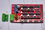
Setting the current of the driver modules – Vref
To make this easy for you, just enter the current phase of your chosen stepper motor and select the driver from the drop-down list.
Once you have this value, turn the trim pot on the driver to match. Watch the Part 2 video to see how to do this.
Check the Steps per Millimetre (Steps/MM)
We need to check that our machine moves the correct distance when it receives a g-code command. So if the g-code says move 50 mm, we need to check it actually moves 50 mm. If not, we need to adjust the steps/mm in the settings page
If you installed the firmware from the website, it will have the correct setting for a 10 mm x 1.5 mm threaded rod using 1/8 micro-steppings. It may need some minor adjustments. But if you’ve used different hardware like 3/8-16 UNC threaded rod or T8 lead-screws, then the values below should be a good starting point.
| Lead Screw/Threaded Rod | Steps per MM 1/8 micro-stepping |
|---|---|
| 10mm x 1.5 mm pitch Threaded Rod | 1066 |
| T8 Lead Screws 2mm pitch | 800 |
| 3/8-16 TPI Threaded Rod | 1007 |
If you are using different hardware, such as a belt drive or a different pitch leadscrew than above, then use the Prusa calculator https://blog.prusaprinters.org/calculator_3416/
It will help you calculate your steps/mm and be a good starting point.
Always check the calibration of whatever type of thread or belt system you use.
Checking the calibration
To check the calibration, place a steel rule on the U-axis (see pic above), then make a pointer that you can align on the rule. Set the pointer on say 300 mm and then in the Manual Command dialogue box type G1 A100 F50 and check how far the pointer has moved. If it has moved to the 200 mm mark on the steel rule, then that’s correct. If not, we need to adjust the steps/mm.

Once you’ve measured the distance moved, enter the details in the form below to get the new steps/mm value
Use the value in New Steps/MM for the values $100-$103 in the settings tab. Make sure you press Enter after entering each setting. I have found that sometimes we need to disconnect from the controller and reconnect to make the settings take effect. Then run the check again, and it should be correct. You will get more accurate results the greater the distance you move the machine. You should at least move 100 mm; any less may not give a good calibration.
Final Checks
If you get inconsistent results, check that all the axes move freely when the power is off. You should be able to turn each threaded rod very easily by hand. Do this slowly, as you can damage the electronics by inducing voltage from the stepper motors. I usually just pull the plugs off the stepper motors before I check this. Check the couplers are tight on the threaded rods and stepper motors. This could cause poor results if they are loose.
The final check is to run a cutting job and see if the part comes out the size you expect. Don’t forget to allow for kerf value. The amount of foam melted by the hot wire. See here how to calculate the kerf.
Use the Clark-Y aerofoil on the download page https://rckeith.co.uk/download/clark-y-wing-200-mm-root-with-spars-and-lightening-holes/ as a test, and you should have a root wing section of 200 mm. If it’s not exactly 200 mm, it could be that the kerf value needs adjusting.
You should now be able to make accurate foam parts.
Happy foam cutting.