PDF Plans to G-code
PDF plans
One of the challenges with any CNC machine is generating g-code. Most foam board plans are PDFs, which need to be converted to g-code to send to a CNC machine. You can use this process for CNC routers, laser and needle cutters
I used this process on my recently USB-converted CNC router to use a needle cutter on the Z-axis. Details are here How to cut foam with a CNC needle cutter

I’ll explain how I create DXF files which I can then generate g-code from. There may be other ways to do this but I find this works well for me. If you know of a better method please let me know.
Just like a laser
The needle cutter operates in the same way as a laser cutter we just use a needle instead of a light beam. So in the CAM software, we use just use the laser kerf setting for the needle width. The laser g-code generated from OpenBuilds CAM worked fantastically.

Overview of my process
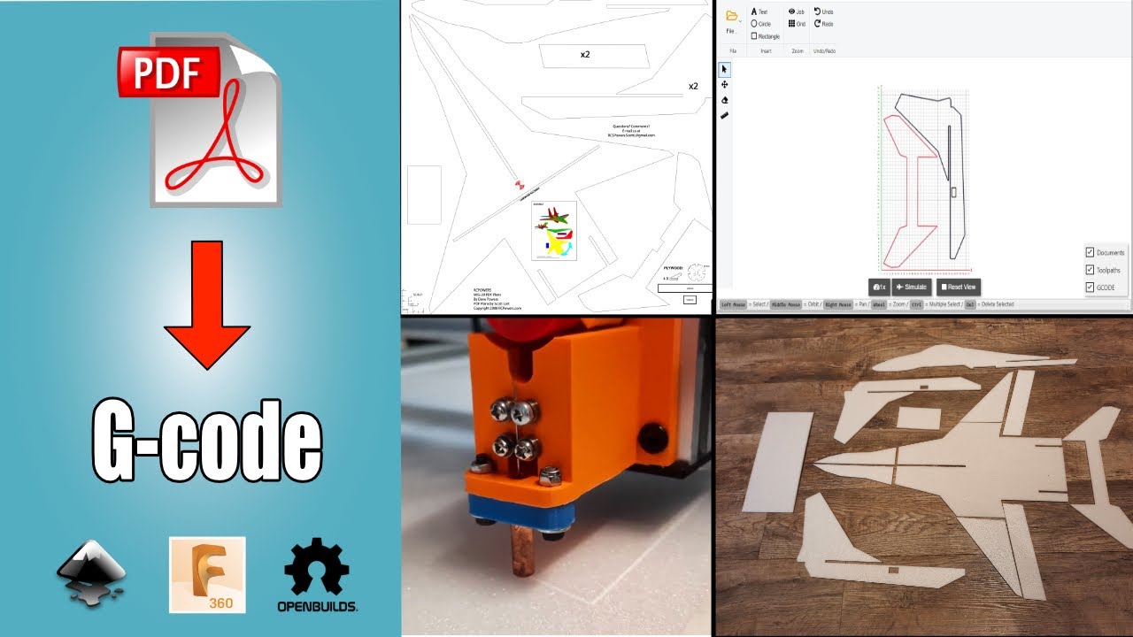
Here is an overview of the basic process I use to convert the PDF plans to DXF format and load these into Openbuilds cam software, which then generates the g-code.
- Use Inkscape to remove unwanted objects from the PDF. e.g. images and text.
- Save as DXF R14 in Inkscape
- Load the DXF file into Fusion 360.
- Fix gaps and create new DXF from bodies.
- Load DXF in Openbuilds CAM to generate the g-code
PDF plans
When you purchase your plans or are using free ones make sure you get an untiled version. Many PDF plans are provided tiled so that you can print them on a standard printer and then join them together. I’ve done this many times. The un-tiled version you usually take to a print shop to get a full-size print.
We need the untiled version for the conversion; otherwise, it will be a lot of work to stitch it all back together.
Where to get PDF Plans from
These are the sites I recommend for plans. The MiG-29 came from RCPowers, and my F18 from FRCFoamies.
If you are looking for free plans, then FliteTest has many. You will need a lot of cleanup in Inkscape with these plans.
- https://jetworks.online/
- https://www.frcfoamies.com/
- https://www.rcpowers.com/post/rcpowers-v5-plansget-them-here-10025854
- https://forum.flitetest.com/index.php?threads/sp0nz-plans-index.17136/
Edit the PDF
I edit PDFs with Inkscape, a free vector graphics program. I used the latest version which I have on my Mac and Windows machines. If the PDF has a lot of objects not required like images and text, it can help the conversion by removing them.

Once loaded into Inkscape, you may need to ungroup the PDF and sometimes you need to do this a few times if there are nested groups so you can delete the unwanted items. Make sure you leave the scale reference on the plan. We need this to check the scale once loaded into Fusion 360.
Save as DXF
Save as a DXF R14. I found that if you save it as SVG, it doesn’t scale well in Fusion 360.
Creating the DXF files using Fusion 360
I use the free version of Fusion 360 for this stage because that is the software I know best. You can manipulate the DXF files in whatever you prefer. I believe the process I show will be possible in most CAD software
Gaps
You will probably find gaps in the DXF imported from Inkscape. These may not be immediately visible but if you zoom in they will appear. If the inside of the profile of the imported DXF isn’t blue, we need to close the gaps. I’ve tried several methods with Inkscape but nothing seems to be able to close them easily. The free Fusion 360 app Sketch Checker shows lines that are not joined.


Please be aware that I won’t be sharing the DXF files out of respect for the guys who have taken the time to design these plans. I have purchased mine, and if you want to follow along then please support these designers and purchase the plans as well.
My process
- Insert the DXF on the top plane.
- Check the scale of the image against the reference scale. You may need to scale the image if incorrect.
- Install the SketchChecker for the Fusion 360 Appstore. This identifies any lines that are not joined. It shows this with a point.
- To fix any unjoined lines, I use extend and trim. Sometimes it’s easier to delete some lines if there are lots of small parts to line and create a new one. This process could take some time if you have a large plan.
- Make sure all objects have a blue profile. If it isn’t, then you need to find the gap and close it. Openbuilds CAM needs a closed vector so the start and finish are the same on the entity you are cutting. https://docs.openbuilds.com/doku.php?id=docs:software:file-errors
- The following processes I found work best for me; there may be other ways to do this.
- Extrude all the sketches into bodies. The distance doesn’t matter, but I usually use the foam thickness of 6 mm

- Create a new component, I call this Sheet1.
- Activate the component.

- Create a new sketch
- Select the geometry of the part or parts you are going put to put on sheet 1 and project the body geometry with the project link unchecked. As the image above
- Move parts to as near 0,0 as possible and ensure they will fit your cutting area.

- Save as DXF

- Load the DXF you’ve just saved into OpenBuilds CAM. This is an online application which is very good and you can run it from here https://cam.openbuilds.com Now follow my video from here https://www.youtube.com/watch?v=Y9-Ccq50j8M&t=791s which will show how to generate the g-code with OpenBuilds Cam

For parts that are too big for the cutting area you have, you will need to break the bodies into smaller bodies that will fit your cutting area and follow the same process as above. There are many tutorials on YouTube showing this. Search for Splitting Bodies in Fusion 360
Summary
This process works well for me, and I have used it to make new foamboard parts for my MiG-29. The tedious part is reconnecting the sketch lines which, if it’s a large plan, could take some time. Check my Mig29 build
I hope this helps with your conversion of PDF plans and if you have any suggestions, then please do let me know via the contact page.