
Electronics Build Guide MKS TinyBee
This guide takes you through setting up the MKS TinyBee electronics for a four-axis CNC hot wire foam cutter. It covers installing FluidNC, testing the motors on the bench, configuring the machine and making your first cut.
The TinyBee uses an ESP32 processor with Wi-Fi. Once the firmware and my foam cutter web interface are installed, you can control the machine from your browser. You use a USB cable for the initial installation, then connect over Wi-Fi to jog the axes, upload G-code and adjust the hot wire.
This is the controller used in my Wi-Fi foam cutter ebook. If you’re building with an Arduino Mega, MKS Gen L or SKR Pico, use the separate guide for that board because the firmware, wiring and settings are different.
MKS TinyBee 32-bit
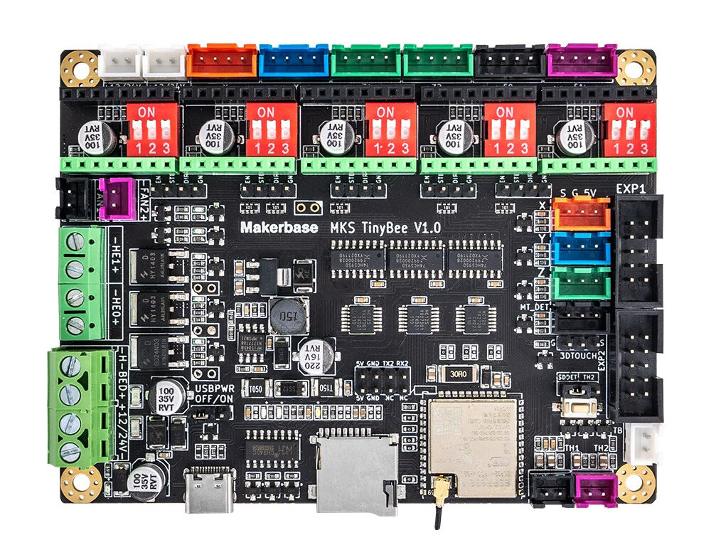
The TinyBee was designed for 3D printers, but with FluidNC and the correct configuration it can control the four independent motors on a foam cutter. The Makerbase board documentation includes the pin map and hardware details.
There are a few useful reasons to choose it:
- Wi-Fi control. You can operate the cutter through its browser interface after the initial setup.
- Replaceable drivers. The stepper drivers plug into sockets, so you can replace a faulty module.
- 12 or 24-volt operation. I use a 24-volt supply for this build.
- Configuration without compiling. The machine settings are stored in
config.yaml. You don’t need to compile a special version of the firmware for your threaded rods or travel distances.
There are also a couple of things to allow for. The hot wire needs a separate PWM MOSFET module, and the driver current is adjusted using the small trim pots on the driver modules. The current settings from the SKR Pico guide don’t apply here.
Build Guide
Start with the foam cutter parts list and the TinyBee wiring details in the ebook. This guide uses four TMC2209 drivers and four NEMA17 motors. If you use different drivers, check their pin layout, microstepping settings and current calculation.
Test the electronics on the bench before fitting them to the foam cutter. It’s much easier to find a faulty cable or incorrect setting when everything is in front of you. Complete the homing test after the switches are installed on the finished machine.
Switch off the power and unplug USB before fitting drivers or changing motor connections. Connecting or disconnecting a motor with the board powered can destroy its driver. Leave the hot wire disconnected until the motion tests are complete.
Step 1 – Connect the board
Connect the TinyBee to your computer with a USB data cable. Some USB cables only provide power, so try another cable if the installer can’t find the board.
Use a Chromium-based browser such as Chrome, Edge or Brave for installation. I’ve confirmed the installation process on Windows 11 and a MacBook Pro. Safari can operate the web interface afterwards, but it can’t be used for this installation process.
If Windows doesn’t detect the serial port, check that the CH340 USB driver is installed. USB power is enough for the installation; it won’t power the stepper motors.
Step 2 – Install FluidNC
Open the FluidNC web installer and connect to the TinyBee’s serial port.
- Select Install FluidNC.
- Choose the Wi-Fi option.
- For a new board, choose a fresh install.
- Follow the installation prompts and wait for the process to finish.
A fresh install can remove existing files and settings, so save a copy first if you’re updating a board you’ve already configured. The installer screens may change between releases, but you need the Wi-Fi firmware for this build.

Step 3 – Upload the configuration and web interface
Download the FluidNC files for the MKS TinyBee and extract the ZIP file on your computer.
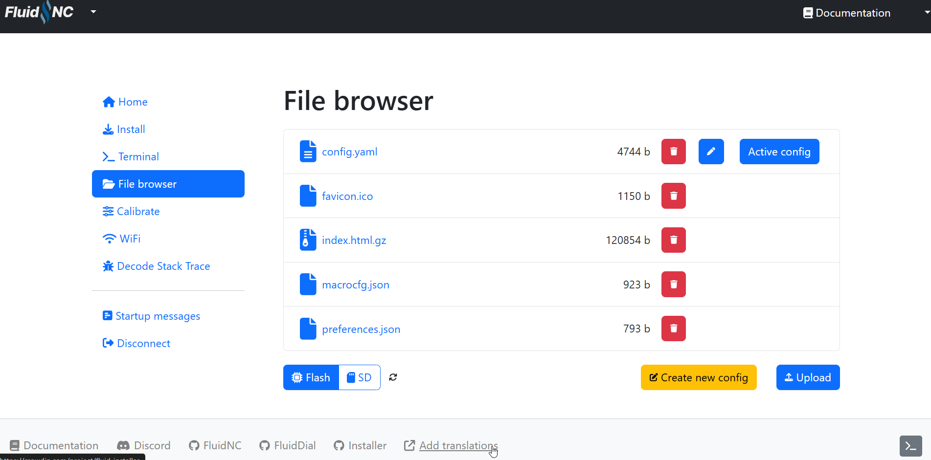
In the installer, open File Browser and upload the extracted configuration and web interface files. Don’t upload the ZIP archive itself. These files provide the four-axis machine configuration and the foam cutter controls adapted from ESP3D-WEBUI.
When the uploads have finished, open the Terminal tab and restart the controller. Check the startup messages for configuration errors before continuing.
Settings used in this build
FluidNC uses named settings in its configuration file. Use the supplied TinyBee file as your starting point; don’t copy the Pico’s numbered settings into it.
| Setting | Starting point for this build |
|---|---|
| Axes | X and A horizontal; Y and Z vertical |
| Microstepping | 1/8, selected on the board’s DIP switches for TMC2209 drivers |
| Steps per millimetre | The ebook uses 1066 for a 200-step motor and M10 × 1.5 mm threaded rod at 1/8 microstepping; check each axis by measurement |
| Driver current | Set with VREF on each driver, according to the motor and driver specifications |
| Hot wire control | External PWM MOSFET, with its trigger connected to GPIO17 |
| Homing order, if used | X cycle 1, Y cycle 2, Z cycle 3, A cycle 4 |
| Maximum travel | Measure the usable travel of your own machine |
Step 4 – Open the Wi-Fi controls
FluidNC can create its own Wi-Fi access point, which is useful if your workshop is outside your home network’s range. Connect your computer to that access point using the details shown by the installer. You can also configure the controller to join your existing Wi-Fi network.
Try http://fluidnc.local in your browser. If it doesn’t open, use the controller’s IP address shown in the connection information or assigned by your router.
You should now see the foam cutter interface. The Motion tab provides the jog controls, and the FluidNC tab includes the hot wire controls and command display.
If the controller reports an alarm, read the message before clearing it. A configuration expecting homing or normally closed switches needs temporary changes for bench testing without switches. Resetting an alarm doesn’t correct an active limit input.
Step 5 – Connect the power supply
I use a 24-volt, 150-watt supply for the TinyBee build. A 12-volt supply can also be used, but the heat available at the wire depends on its length, diameter and material. In my experience, a wire around a metre long can be near the practical limit of 12 volts when using 0.4 mm nichrome.
With the supply unplugged, connect its DC output to the TinyBee’s power input, checking the positive and negative markings carefully. If your supply has a mains voltage selector, set it correctly before powering it.
Take care with mains wiring. If you’re unsure, get professional help.
Power the controller and check that you can still open the web interface.
Step 6 – Set the microstepping
Microstepping divides each full motor step into smaller movements. I use 1/8 microstepping with the TMC2209 drivers, which works well on this foam cutter.
For the TMC2209 modules used here, set M1 OFF, M2 OFF and M3 OFF on each of the four driver positions. Keep M3 off; switching it on can cause problems with these modules.
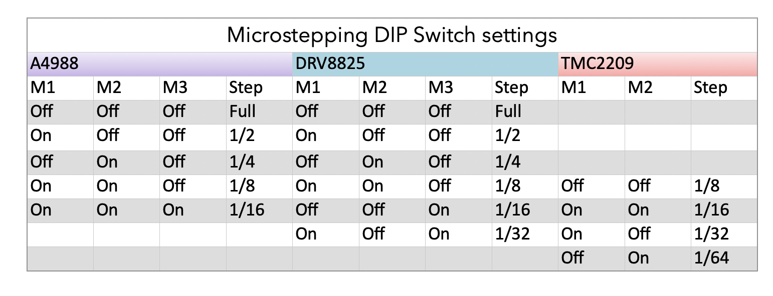
If you change the microstepping, you must also change the steps/mm. Otherwise, a commanded move won’t travel the distance you expect.
Step 7 – Fit the stepper drivers
With both USB and the power supply disconnected, fit the four TMC2209 modules in the positions shown by the TinyBee wiring diagram in the ebook.
Match the driver’s EN pin to the EN position on the board. Don’t use the trim pot’s position as your guide because different modules can have different layouts. Fitting a driver backwards is likely to damage it.
Fit the heatsinks supplied with the modules, making sure they don’t bridge any electrical contacts.
Step 8 – Set the driver current
VREF is the reference voltage that sets the motor current. Too much current makes the motor and driver hot; too little can cause missed steps or prevent the motor moving.
Find the motor’s rated current per phase, then use my driver current and VREF calculator. Select the correct driver and check its module specifications. Don’t assume one VREF value suits every TMC2209 module.
The ebook uses around 80% of the motor’s rated current as a starting point, provided this is within the driver module’s limits. The aim is the lowest current that moves the machine reliably without excessive heat.
- Set your multimeter to DC voltage.
- With the controller powered, connect the black probe to GND.
- Carefully touch the red probe to the driver’s VREF test point.
- Adjust the trim pot with a ceramic or other non-conductive screwdriver until the required voltage is reached.
- Repeat for all four drivers.
Take your time: a slipped probe can short nearby contacts. Disconnect all power before changing any motor wiring.
Step 9 – Connect and bench test the motors
With the power off, connect the four motors using the socket assignments in the ebook’s wiring diagram. The axis letters refer to the foam cutter movements, so check the supplied configuration when identifying the board’s motor sockets.
Before jogging without limit switches, save a copy of the original configuration. In the configuration editor, temporarily disable homing and soft and hard limits, disable the requirement to home on startup, and set unused limit inputs to NO_PIN. This prevents disconnected normally closed inputs being treated as triggered switches. Save and restart the controller.
Power the motors and try a short jog on each axis. Each motor should turn smoothly in both directions. If one only vibrates or runs erratically, switch off and check its two coil pairs. Cable colours aren’t a reliable guide.
My stepper motor wire pairing video explains how to check the pairs. The video shows older hardware, but the method is the same.
Step 10 – Fit the cooling fan
Don’t skip the fan. The plug-in drivers get hot, especially when enclosed in a case. I use a 60 mm, 24-volt fan to move air over the driver heatsinks.
Connect the fan directly to the DC supply, using a fan rated for that voltage. Don’t use the TinyBee sockets marked FAN for this setup.
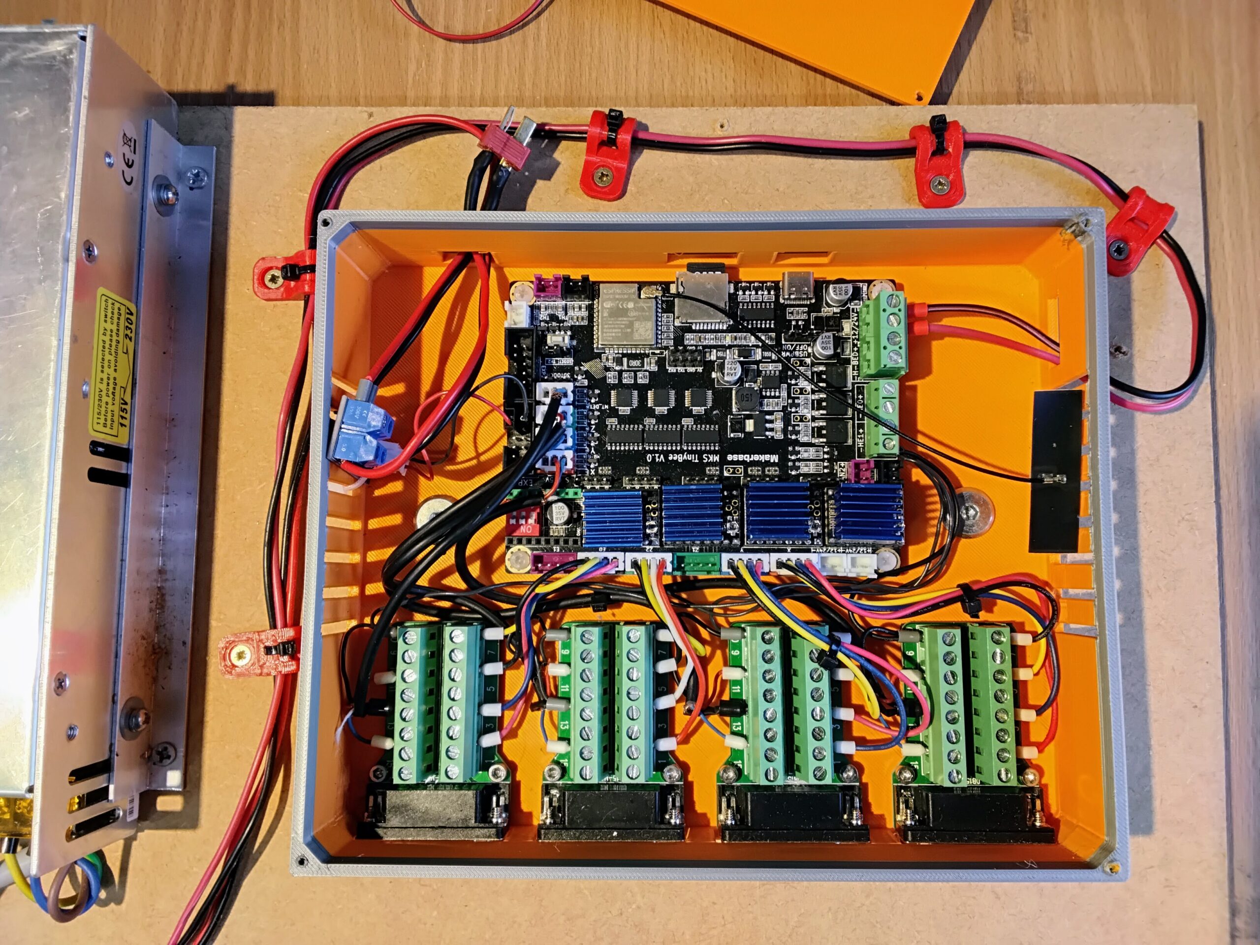
Run the motors on the bench and check for excessive heat. Correct a current setting or cooling problem before fitting everything to the machine.
Step 11 – Complete the foam cutter build and wiring
Once the electronics work on the bench, complete the mechanical build using the ebook and plans. Before connecting the motors, check that the threaded rods or leadscrews turn freely without binding.
Disconnect the motors from the controller before turning them by hand. A turning stepper motor generates voltage, which can feed back into the electronics.
Extend the motor cables with wire of the same gauge or larger and keep the coil pairs together. Secure the connections and leave enough cable for the full travel of each carriage.
If you’re fitting homing switches, use screened cable and route it away from the motor and hot wire power cables.
Step 12 – Keep homing disabled for the direction test
Leave the temporary bench-test settings in place while checking the axis directions. Homing comes later, once normal jogging works correctly and the switches have been tested.
FluidNC’s axis configuration documentation explains the named settings. This build uses the installer’s configuration editor rather than the Pico guide’s $22 setting.
Step 13 – Check the axis directions
With the power off and the motors disconnected, move each carriage away from its physical stops. Reconnect the motors, power up and open the Motion tab.
Start with a 1 mm jog. On this design, X+ and A+ move the horizontal carriages towards you, while Y+ and Z+ move the vertical carriages upwards.
If an axis moves the wrong way, connect by USB to the FluidNC installer, open File Browser and select the edit icon for the configuration file. Find that motor’s Direction pin setting and change its Invert checkbox. Save, restart and test again.
Check all four axes before continuing. A short jog gives you time to spot a wrong direction before a carriage reaches a stop.
Step 14 – Check the calibration
Steps/mm tells the controller how many step pulses produce one millimetre of carriage movement. For a directly driven screw:
Steps/mm = motor full steps per revolution × microsteps ÷ screw travel per revolution in mm.
For a 200-step motor at 1/8 microstepping, the calculated starting values are:
| Threaded rod or leadscrew | Travel per revolution | Calculated steps/mm |
|---|---|---|
| M10 × 1.5 mm threaded rod | 1.5 mm | 1066.67 |
| 3/8–16 TPI threaded rod | 1.5875 mm | 1007.87 |
| Leadscrew with 2 mm lead | 2 mm | 800 |
| Leadscrew with 8 mm lead | 8 mm | 200 |
The ebook rounds the first two values to 1066 and 1007. Use the calculation as a starting point, then measure your machine.
Check the lead of a T8 screw. Its pitch alone doesn’t tell you how far the nut travels in one revolution. A screw with a 2 mm pitch and four starts moves 8 mm per revolution. If you’re unsure, turn it once and measure the nut’s movement.
Place a rule alongside an axis and attach a pointer to the carriage. With enough clear travel, command a known jog distance, such as 50 mm, and measure the actual movement. Repeat for each axis.
If adjustment is needed, use my steps/mm calibration calculator, enter the new value in the configuration editor, save and restart. Check the distance again.
Step 15 – Configure homing if required
You can use the cutter without homing switches by jogging to your chosen start position and setting the work coordinates to zero. If you want homing, install and test the switches on the machine before enabling it.
I use four normally closed switches: one for each axis. Connect each switch’s Common and NC terminals to the relevant input’s Signal and Ground pins. Don’t connect the 5-volt pin for these mechanical switches. Connect the cable screen at the controller end only.

Restore the limit input assignments from your saved configuration and check the input status. Each switch should show clear when released and triggered when pressed. Stop here if the display doesn’t agree with the physical switch.
Enable homing in the configuration editor. I prefer to home the axes individually, with X set to cycle 1, Y to cycle 2, Z to cycle 3 and A to cycle 4. Axes sharing a cycle number home together.
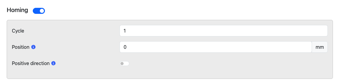
Keep the supplied homing position and direction as your starting point. If jogging is correct but an axis homes the wrong way, change its homing Positive direction setting. Save and restart after each change.
Run the first homing cycle with the hot wire off and be ready to stop the machine. I use a 2 mm pull-off with screened switch cables. Check that each axis backs away far enough to release its switch.
After homing works reliably, measure the usable travel and set max_travel_mm for each axis before enabling soft limits. Soft limits use the homed position to prevent moves beyond the configured travel. Enable hard limits only after confirming the physical inputs work correctly.
Step 16 – Run the machine with the wire off
Download the Clark-Y XYZA sample G-code and upload clarky-test-200mm_XYZA.nc using the web interface’s file controls. Use the XYZA version to match this configuration.
Keep the hot wire disconnected and leave the cutting area clear. Home the machine, or set the work coordinates to zero at a suitable starting position if you aren’t using homing. Check that the sample path fits within the available travel, then run it.
Watch all four axes. Resolve any binding, missed steps, incorrect movements or cable snagging before adding heat or foam.
Step 17 – Connect and test the hot wire
The TinyBee’s onboard heater outputs aren’t used for variable hot wire power in this FluidNC setup. Fit the separate PWM MOSFET module specified for the build.

With all power disconnected, make these connections:
- TinyBee GPIO17 to MOSFET TRIG/PWM. The ebook’s EXP1 drawing identifies this as physical pin 3 when viewed with the key notch facing down.
- TinyBee GND to MOSFET control GND. In that same drawing, physical pin 2 is ground. This means GND, not GPIO2.
- Power supply DC output to MOSFET VIN+ and VIN−.
- MOSFET VOUT+ and VOUT− to the hot wire connections.
Check the header orientation and the markings on your own module before powering it. GPIO17 carries the control signal; the wire’s heating current goes through the MOSFET’s power terminals.
I now use a bow to tension the wire, so the tension stays within the bow rather than pulling on the carriages. A spring can also work, but avoid excessive tension, particularly with swept wings.
In the Hot Wire controls, start with a low heat percentage, such as 10%, and switch the wire on. Test it with scrap foam, keeping your fingers clear. Increase the setting gradually until it cuts without being dragged through the foam. Use ventilation while cutting.
The percentage controls the PWM duty cycle, which changes the heating power. It isn’t a measured temperature or current. Switch the wire off after the test.
Step 18 – Make the first cut
Use scrap foam for the first cut. Secure it with double-sided tape or a small weight, keeping both clear of the wire’s path. Position the block as required by the sample file, jog the wire to the starting point and zero the work coordinates.
Set the heat to the value found during testing, allow the wire to warm up and run the sample. Use the Override tab to adjust the heat while the job runs.
Look down on the wire. If it bends behind the moving carriages, it’s dragging and needs more heat or a slower feed rate. If it melts a wide gap, reduce the heat and test again.
The gap melted away is called the kerf. Once you have a clean cut, measure it so your design software can allow for the material removed. My guide to getting a good kerf setting explains the test.
Don’t expect every foam or wire to use the same setting. I still make test cuts before committing a good block of foam.
Step 19 – Generate G-code for your projects
With the machine working, you can start cutting your own wings and fuselage sections. See my foam cutting software guide for the available options.
I use DevWing Foam 2 and DevFus Foam for my projects. Free programs can be a useful starting point for simple wings, so try them with the designs you want to make before buying software.
Make sure the output uses the correct axes: X and A horizontal, Y and Z vertical. Preview a new file and run it with the wire off before cutting foam. That simple check is much cheaper than finding an unexpected move halfway through a wing.